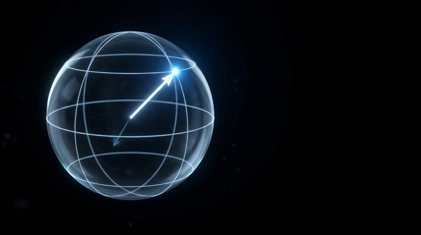
Every gate so far has been a rotation with the angle welded shut: 180° for the Paulis and H, 90° for S, 45° for T. The rotation gates Rx, Ry and Rz take the weld off and give you a dial.
That one change is the difference between a handful of fixed moves and complete control of the qubit. This part shows why two dialled rotations are enough to reach any state on the sphere, and why that fact is the reason your circuits look nothing like what you wrote after the compiler has finished with them.
A rotation you choose
Set the slider to 45° and press Ry.
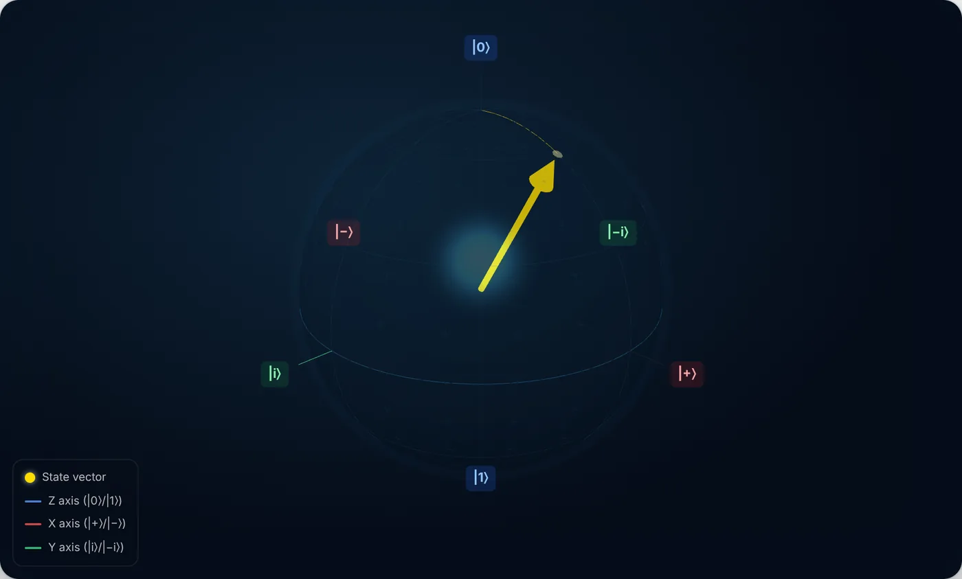
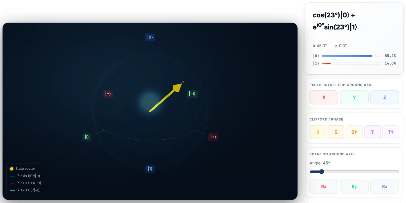
This is the first gate in the series that can produce a biased qubit. H gives you 50/50 whether you like it or not. Ry(45°) gives you 85.4/14.6, because P(0) = cos²(45°/2) = cos²(22.5°) = 0.854. Any bias you want is one slider away, which is what state preparation actually is.
Rx behaves the same way about the red axis:
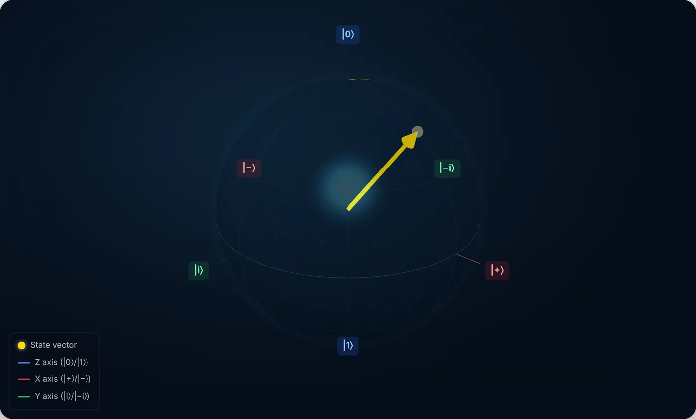
Turn the dial to 180° and you get the Pauli gates back. Rx(180°) does to the sphere exactly what X does. Strictly the matrices differ by a factor of −i, but that is a global phase, and Part 2 showed why the sphere is entitled to ignore it. The Paulis are the ends of these dials, not separate machinery.
Why the angle is halved
Ry(45°) moved the arrow 45° on the sphere, and the simulator’s θ readout says 45°. So where did the “half angle” of Part 1 go?
It is in the matrix, not the picture. The rotation gate is defined as:
Ry(α) = exp(−i α Y / 2) = cos(α/2)·I − i·sin(α/2)·Y
The α/2 inside the gate and the θ/2 inside the state cancel out exactly, which is the whole reason the Bloch picture is worth having: the angle you dial is the angle the arrow sweeps. Underneath, the state vector in Hilbert space only turned half as far. A 360° rotation brings the arrow home but leaves the state at −|ψ⟩, and only a 720° turn restores the state itself. That is the notorious spin-1/2 double cover, and on the sphere you get to enjoy the benefit while ignoring the bookkeeping.
Two rotations reach everything
Here is the payoff. A state is just two angles, θ and φ. You have a gate that sets each of them:
- Ry(θ) tips the arrow down from the north pole by θ. That fixes the latitude.
- Rz(φ) spins it around by φ. That fixes the longitude.
So starting from |0⟩, Ry then Rz reaches any point on the sphere. Try it: set the slider to 70°, press Ry, set it to 130°, press Rz.
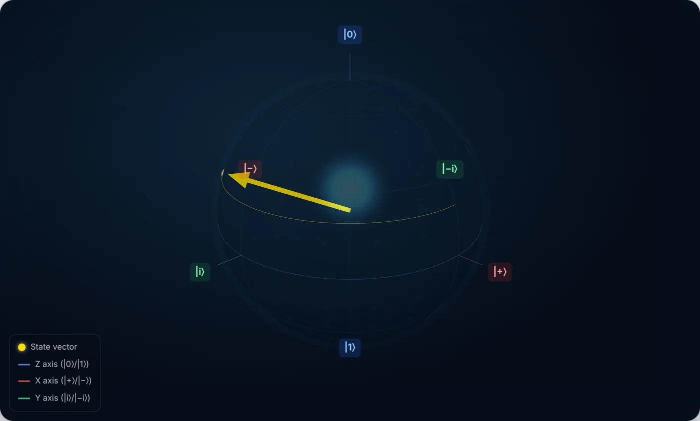
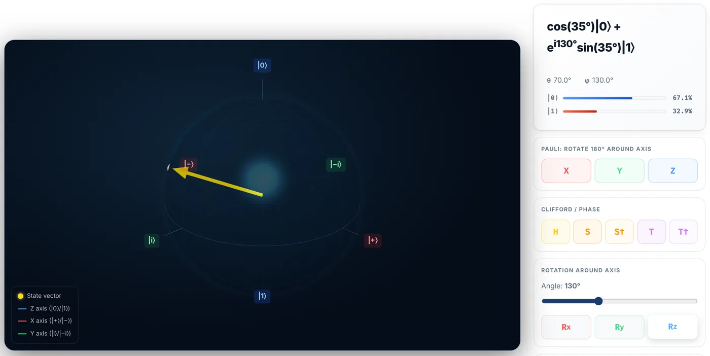
The readout gives back precisely the numbers you asked for. There was no searching, no optimisation, no cleverness: latitude then longitude, and any state on the sphere is two gates away.
That is universality for a single qubit, and it is why hardware vendors do not need to give you a hundred gates. Any single-qubit unitary whatsoever can be written as three rotations:
U = Rz(γ) · Ry(β) · Rz(α) (up to a global phase)
Three angles, because a general unitary also has to say what it does to every state, not just to |0⟩. These are the Euler angles, the same ones used to orient an aircraft, for the same reason: both problems are “describe an arbitrary rotation of a sphere”.
What your transpiler is really doing
This is not decorative theory. It is the core of transpilation.
Real hardware does not implement H, or T, or the gate you actually wrote. A superconducting processor typically offers a native gate set of roughly rz, sx (a 90° X rotation) and x, plus one two-qubit gate. Every single-qubit gate in your circuit gets rewritten into that alphabet, and the Euler decomposition is the tool that does the rewriting.
There is a lovely piece of hardware trickery hiding here. On superconducting qubits, Rz is free. It is not executed as a physical pulse at all: the control electronics simply relabel the phase reference for every subsequent pulse, a “virtual Z”. Zero duration, zero error. Rotations about X and Y need real microwave pulses, which take time and add noise.
So the decomposition above is not merely one valid choice among many. It is the economical one, pushing as much of the work as possible onto the free axis. Watch Qiskit do it:
import numpy as np
from qiskit import QuantumCircuit, transpile
from qiskit.quantum_info import Statevector

# The state from the screenshots: theta = 70, phi = 130.
qc = QuantumCircuit(1)
qc.ry(np.radians(70), 0)
qc.rz(np.radians(130), 0)

sv = Statevector(qc)
p0 = abs(sv.data[0]) ** 2
print(f"P(0) = {p0 * 100:.1f}%   P(1) = {(1 - p0) * 100:.1f}%")
print(f"cos^2(35 deg) = {np.cos(np.radians(35)) ** 2 * 100:.1f}%")
P(0) = 67.1%   P(1) = 32.9%
cos^2(35 deg) = 67.1%
The 67.1/32.9 split is exactly what the simulator’s probability bars showed. Now hand the same circuit to the transpiler and ask for hardware-native gates:
native = transpile(qc, basis_gates=["rz", "sx", "x"], optimization_level=3)
print(native)
print("gate counts:", dict(native.count_ops()))
global phase: π/2
   ┌────┐┌─────────────┐┌────┐┌──────────────┐
q: ┤ √X ├┤ Rz(-1.9199) ├┤ √X ├┤ Rz(-0.87266) ├
   └────┘└─────────────┘└────┘└──────────────┘
gate counts: {'sx': 2, 'rz': 2}
Your Ry and Rz came back as four gates, and that looks like a loss until you count what will actually cost you anything. The two rz gates are free, so the whole state preparation costs two physical pulses, the two √X. The transpiler has rebuilt your Ry out of the free rotation and the one real pulse the hardware owns, sandwiching phase shifts around fixed 90° X pulses.
This is also why the gate count printed by a transpiler is a bad proxy for how hard a circuit is to run. Ask instead how many pulses, and how many T gates.
Interrogating the decomposition yourself
Qiskit will hand you the Euler angles for any single-qubit unitary directly:
from qiskit.quantum_info import Operator
from qiskit.synthesis import OneQubitEulerDecomposer

decomposer = OneQubitEulerDecomposer(basis="ZYZ")

for name in ["H", "X", "S", "T"]:
    theta, phi, lam, _ = decomposer.angles_and_phase(Operator.from_label(name).data)
    print(f"{name}:  Rz({np.degrees(lam):7.1f})  Ry({np.degrees(theta):7.1f})  Rz({np.degrees(phi):7.1f})")
H:  Rz(  180.0)  Ry(   90.0)  Rz(    0.0)
X:  Rz(    0.0)  Ry(  180.0)  Rz( -180.0)
S:  Rz(   90.0)  Ry(    0.0)  Rz(    0.0)
T:  Rz(   45.0)  Ry(    0.0)  Rz(    0.0)
The gates are listed in the order they would run, left to right. Read the table and every claim in this series is confirmed at a glance.
S and T have no Ry component at all. They are bare Z rotations, 90° and 45°, which is exactly why Part 3 found them doing nothing whatsoever to states parked on the Z axis.
X is a 180° Y rotation with a Z shuffle attached. There is more than one route to the south pole, and the decomposer picked a different one from the X axis, which is fine: any of them produce the same unitary.
H is Rz(180°) followed by Ry(90°). Feed |0⟩ into that and the Rz does nothing (|0⟩ is on its axis), then the 90° tip drops it onto the equator at |+⟩. The famous superposition gate is a phase flip you cannot see followed by a quarter-turn you can.
Where the sphere runs out
You can now put a single qubit anywhere you like, with two gates, and you know what the compiler will turn them into.
Which is the natural moment to ask what this picture cannot do. It has no way to draw an entangled pair. It has no way to draw a qubit that is decohering. And it has said nothing yet about what happens at the only moment that matters, when you measure.
Part 5 is about the edges of the map.